GMC WESTERN STATES
MOTORHOME CLUB
 ONAN CONTROL BOARD
OPERATION
Prepared By: Duane M. Simmons
March 18-23, 2001
2001 Spring Roundup, Palm Desert, CA
1
Table of Contents
General Information
Motor
Generator Schematic
Circuit
Board Schematic
Start
Circuit Schematic
Run Circuit
Schematic
Stop
Circuit Schematic
LOP Circuit
Schematic
Emergency
Stop - Start Procedure
LOP Circuit Test Procedure
Remote Contol Panel Fuel
Priming Circuit
Control Board Removal
and Replacement Procedure
General Repair
Procedure
After Market Control
Boards
General Control
Trouble Shooting Guide
Trouble Shooting
Aids:
Trys to Run
with Start Switch On
Will Not Try to Run (Starter
OK)
Remote Control Panel
is Non Functional
No Starter Action
No Response to Stop Switch
General Repair Comments
Board Repair and Technical
Assistance
|
Many thanks to Len Mortimer for the
cover art work & all thiose GMC Pacific Cruisers that reviewed
this document prior to publication.
Copyright 1999
The contents of this document are based
upon personal experience gained by "Hands-On" vehicle
maintenance over many years. They are "One Man's" viewpoint
& do not prepresent authorized data pertaining to the GMC
Motorhome.
It is the Reader's responsibility to establish his/her position
associated with each subject matter before vehicle repair and/or
modifications are accomplished. |
2
ONAN
MOTOR GENERATOR
GENERAL INFORMATION
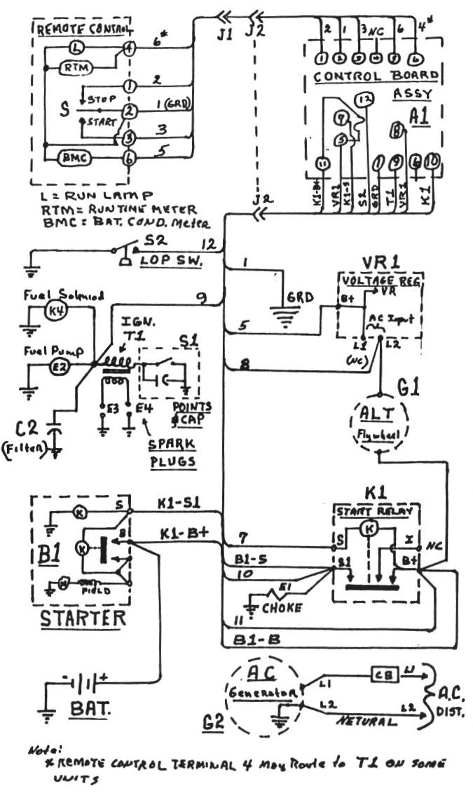
The Onan Motor Generator is powered by
a two cylinder - four cycle horizontally opposed gasoline engine.
An automotive type starter is used to start the engine. The starter
is powered by a battery located in the motor generator compartment.
A permanent magnet flywheel alternator and solid state voltage
regulator is used to charge the battery on the initial coach
configuration (dedicated onan battery, most have been upgraded
to share battery with house and are charded via the engine alternator
and AC to DC converter).
Lubrication is provided by an oil system
with a spin-on type oil filter.
The Motor Generator's electric fuel pump
draws fuel from the vehicle's main fuel tank.
A Control Circuit Board provides control
functions for operation including the following:
(a) Ignition start and stop control
(b) Fuel pump and fuel solenoid control
(c) Automatic starter disconnect
(d) Circuit fuse protection
(e) Automatic delayed los oil pressure condition shut-down
(f) Electric choke operation
(g) Remote control capability
3
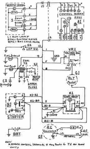
MOTOR GENERATOR WIRING DIAGRAM
Large
View
 4
4
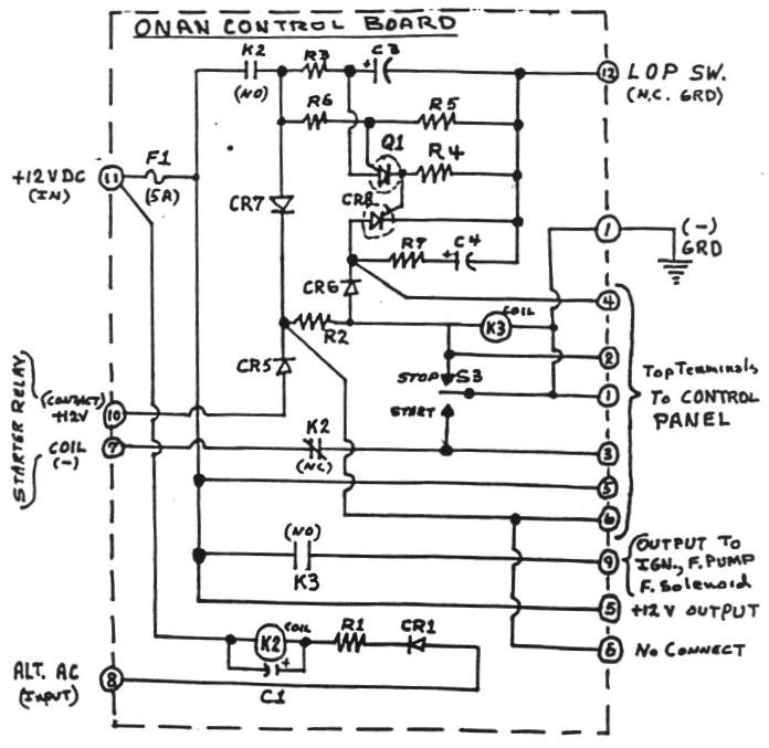
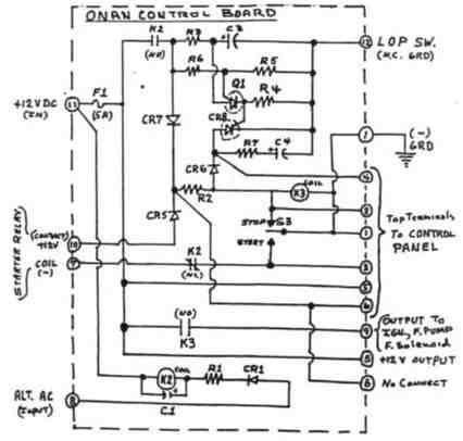
CIRCUIT
BOARD SCHEMATIC DIAGRAM
Large
View
 5
5
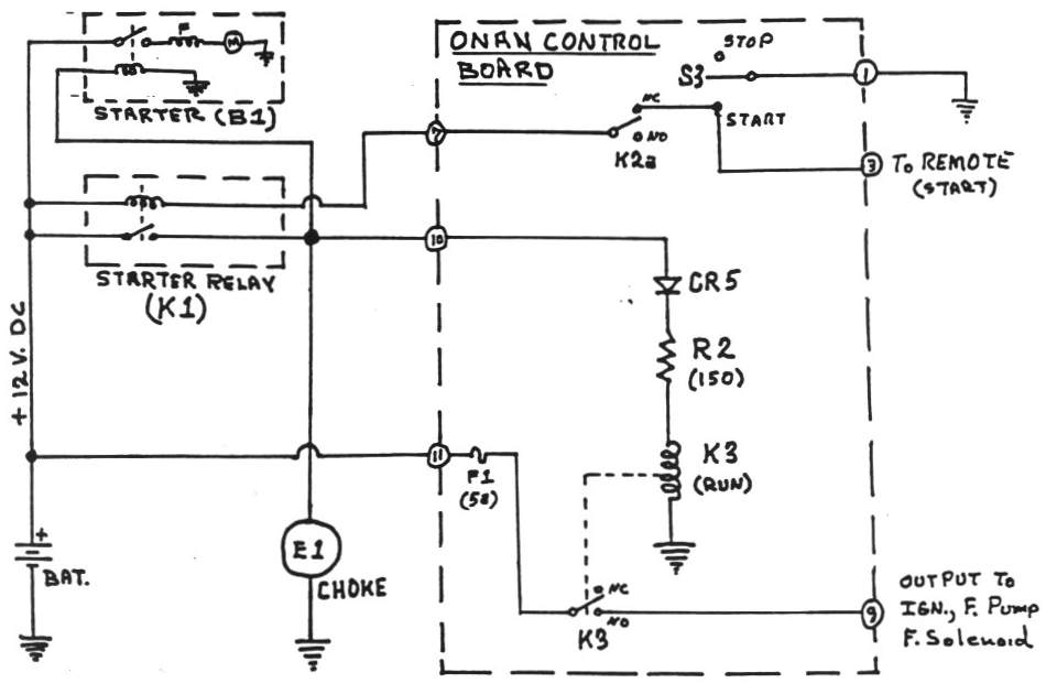
FIGURE 1
START
CIRCUIT SCHEMATIC DIAGRAM
Large
View
 6
6
STARTING CIRCUIT [Figure 1]
Pressing the "START" switch (S3
or the Remote Switch) will power the starter relay [K1] by applying
a ground through the "HOLD RELAY" contact K2a (normally
closed contact)
When the "Start" relay [K1] is
energized it activates:
(a) Starter solenoid and starter motor
[B1]
(b) Electric choke solenoid [E1]
(c) "Run Relay" [K3] thru CR5 and R2
The "Run Relay" contact [K3]
(normally open) applies power to the following:
(a) Fuel pump [E2]
(b) Fuel solenoid [K4]
(c) Ignition coil [T1]
Resulting action: Engine starts and runs
7
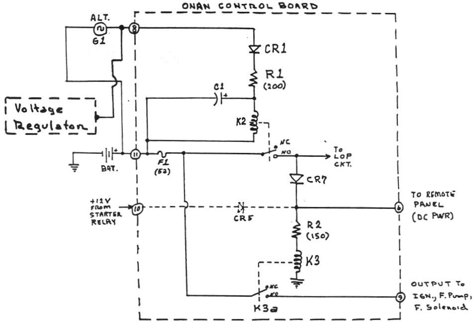
FIGURE 2
RUN
CIRCUIT SCHEMATIC DIAGRAM
Large
View
 8
8
RUNNING CIRCUIT (Figure 2)
The output (AC voltage) of the alternator
[G1] increases as the engine speed increases. This AC voltage
is converted to DC voltage by Diode [CR1], Resistor [R1], and
Capacitor [C1] and is applied to the "Hold Relay" coil
[K2].
The "Hold Relay" [K2] is energized
when the applied voltage reaches 10 to 11 volts DC (typical).
One contact of [K2} opens to disable the start circuit ([K2a]
- See Fig. 1) and the second contact [K2b] closes to apply power
to the following:
(a) "Run Relay" coil [K3]
(b) Remote control panel
(c) The low oil pressure (LOP) circuit.
9
FIGURE 3
STOP
CIRCUIT SCHEMATIC DIAGRAM
Large
View
 10
10
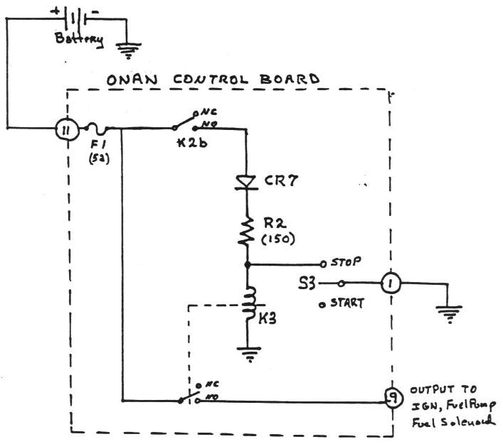
STOPPING CIRCUIT (Figure 3)
Pressing the "STOP" switch (S3
or Remote Switch) will short out the "Run Relay" coil
[K3] which de-energizes and removes power from the following:
(a) Fuel pump [E2]
(b) Fuel solenoid [K4]
(c) Ignition coil [T1]
Resistor [R2] limits the short circuit
current thru the "Run Relay" coil [K3] and Diode [CR7]
As the engine speed decreases, the AC voltage
output of [G1] decreases to a potential where the "Hold
Relay" [K2] de-energizes and drops out (opens). This action
removes power from the "Run Relay" coil [K3], the remote
control panel and the low oil pressure circuit. The action also
resets the [K2a] contact to the starting position for future
starts.
Resulting action: Engine stops and resets
starting circuit.
11
FIGURE 4
LOW
OIL PRESSURE (LOP) CIRCUIT SCHEMATIC DIAGRAM
Large
View
 12
12
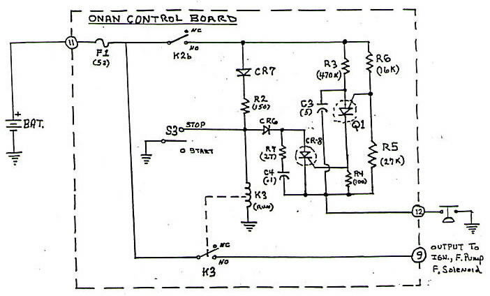
LOW OIL PRESSURE (LOP) CIRCUIT
(Figure 4)
The engine opl pressure activates the LOP
switch [S2] to an open condition (no connection) for normal engine
operation. However, if a low oil pressure condition exists, the
LOP switch activates the LOP circret by applying a ground to
control board terminal 12.
Power (+) is applied to the LOP circuit
by the "Hold Relay" [K2} after the engine starts. With
power applied and the LOP switch closed (low oil pressure condition),
the circuit is complete and capacitor [C3] starts to charge thru
resistor [R3]. When capacitor [C3] reaches the level of the voltage
divider resistors [R5 - R6], the programmable unijunction transistor
[Q1] fires (conducts) and the charge on capacitor [C3] is conducted
thru resistor [R4} to the gate of the silicon controlled rectifier
[SCR-CR8], which puts it in a conducting state [on]. Resistor
[R7} and capacitor [C4] prevents unintentional operation of the
SCR [CR8].
Typical time delay is 3 to 5 seconds
The energizing current that holds the "Run
Relay" coil [K3] during "Engine Run" is routed
(shunted) to ground via the diode [CR6], the SCR [CR8] and the
LOP switch [S2], effectively shorting out the "Run Relay"
coil [K3] which then opens (drops out), shutting down the engine
as noted in the "Stopping Circuit" description (Fig
3).
Note: LOP circuit is reset (initialized)
upon power removal
13
EMERGENCY
START / STOP PROCEDURE
Bypass circuit board (all functions except
fuse) as follows:
! Jumper
terminal 9 to 5 (fused power) - This will energize the fuel pump,
fuel solenoid and ignition coil
! Press the "Start Switch" [S3] or temporarily
jumper terminal 1 to 7 - This will engage the starter. Remove
jumper as soon as the engine starts. Note: Do not press switch
or jujper terminal 1 to 7 while engine is running.
! Remove jumper from terminal 9 to 5 for engine stop
|
CAUTION: This emergency / test operation does not provide
starter disconnect or Low Oil Pressure shutdown protection and
should not be used without monitoring the motor generator. |
For Emergency and Test Situations
Only
14
LOW OIL
PRESSURE (LOP) CIRCUIT TEST PROCEDURE
Verify board low oil pressure (LOP) circuit
operation as follows:
Engine running under normal conditions
Jumper terminal 1 to 12 and measure time required for engine
to stop
Typical delay time should be 3 to 5 seconds
Remove jumper and re-start engine
Board test complete
Circuit board is OK with 3 to 5 seconds time delay
Circuit board Malfunction if no time delay or if engine does
not stop
LOP switch and wiring test
Remove wire from board terminal 12
Measure resistance to ground of wire 12
Without engine operating, should be near zero ohms
With engine operating, should be high resistance (open)
Test complete: Attach wire to terminal 12 and start engine
Note: A malfunction LOP circuit could cause
permanent engine damage due to operation with loss of oil pressure.
15
REMOTE
CONTROL PANEL FUEL PRIMING CIRCUIT
Modify remote control panel wiring with
the following:
5 amp fuse and fuse holder
5 amp diode (50prv)
Momentary switch (5 amp)
Hook-up wiring
Locate local +12 volt source and connect
fuse holder
Drill hole in panel and mount momentary
switch
Connect fuse holder to anode end of diode
Connect cathode end (with band) of diode
to switch (input)
Connect switch output to start / stop switch
terminal that is activated with +12 VDC while the Onan is running
Also wire is present between switch terminal and RTM if so equipped
Press and hold momentary switch for 10
to 30 seconds to prime carburator prior to start function
Circuit diagram: 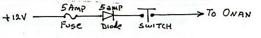
12
CONTROL
BOARD REMOVAL AND REPLACEMENT PROCEDURE
Pull out Onan drawer and remove board metal
protective cover (Right side / 2 screws) and lightly spray board
terminals with WD-40, 2-26 or equal.
Remove wire from board terminal 11 (Input
Power), Tape wire and set aside.
! Note: Care should be taken in removing wires due
to fragile terminal design.
Remove one wire at a time and verify wire
marking of terminal number.
! Note: Wires are marked with terminals numbers.....Don't
cross them.
Verify remote control wire function (upper
terminals) before install.
! Carefully identify each wire function with ohmmeter
and an assistant to activate the remote control switch. Verify
the wires are not interchanged (crossed) or shorted to ground
within the coach.
Install control board with 4 mounting screws.
Attach each wire to board terminals using
positive ID of wire markings.
! Remove tape from wire 11 and attach to board terminal
11.
Install cable ties and board metal protective cover
Press / Hold "Start Switch" and
verify Run / Stop operation.
17
GENERAL
REPAIR PROCEDURE
Clean circuit board and terminals with
degreaser, soap and water (avoid water in the switch and relays).
Low heat to dry board
Test, isolate, remove and repair malfunctioning
component(s).
Replace CR5 diodes with 1N4004 (400 volt,
1 amp) or equal.
Due to potential damage from the choke solenoid high voltage
"Kick Back". Also replace CR1 and 6 with IN4004 diode
or equal.
Replace CR7 diodes with 1N4004 (400 volt,
1 amp) or equal
Due potential damage from CR5 failure (also replace CR1 and 6)
Replace K2 and K3 if contacts are burned
or non-functional
Apply electronic printed circuit board
protective conformal coating (acrylic resin, type AR) to printed
circuit side (bottom side) and non-terminal area of component
side (top side)...several coats
Apply anti-oxidant grease on all terminals
(protective coating)
Test and verify all circuit board functions
18
AFTER
MARKET CONTROL BOARDS
Stay away
from after market boards
No documentation of circuit
No valid trouble shooting procedure
Onan company repair centers will not work on a generator with
a bogus control board. It must be replaced with a genuine Onan
control board before repair @ $$$$$$
19
GENERAL
CONTROL TROUBLE SHOOTING GUIDE
Clean battery cables (both + and - cables
/ both ends)
! Apply corrosion prevention material to cable ends and
mating surfaces.
Remove upper board terminal wires (Leave
disconnected for test)
! Verify operation of remote control panel and that wires
are not shorted to ground.
Remove wire from board terminal 12 (Leave
disconnected for test)
! Verify oil pressure switch and wire operation (not shorted
to ground).
Remove wires (Typically 2 or 3) from voltage
regulator. Note wire location
! Tape up single terminated wire and 2X terminated wires
separately
! Permanently stow (voltage regulator is not required).
Disconnect 12 pin connector [J2]
! Clean and re-shape female sockets for round shape.
Verify fuse [F1] is 5 amp and is functional
! Terminal 5 to 1 or each fuse holder clip to 1 is +12VDC
Verify fuel present at carburator:
! Disconnect at fuel pump and jumper board terminal 9
to 5
Verify ignition functional - spark present
! Jumper board terminal 9 to 5 and make and break points
Verify voltage / resistance levels
|
Terminal |
|
|
12 to 1 |
greater than 10 ohms (starter on and
wire on) |
|
10 to 1 |
less than 0.5 volts DC |
|
8 to 11 |
26 to 30 volts AC (Onan running) |
|
10 to 1 |
greater than 10 volts DC (starter on) |
|
9 to 1 |
greater than 10 volts DC (starter on) |
|
1 to (-) bat |
near 0 ohms |
|
11 to 1 |
greater than 10 volts DC (starter on) |
20 - 21
TROUBLE
SHOOTING AIDS
TRYS
TO RUN WITH START SWITCH ON
Battery charge verified, battery cables
clean and functional, control board fuse (5a) OK, and oil level
verified
Attach jumper board terninal 9 to 5 - should
hear fuel pump running
Press start switch and Onan runs
Remove jumper and Onan continues to run
Suspect
low battery voltage between terminal 11 to 1 (with starter on)
! Must be greater than 10.5 VDC (typically 11.5 VDC
Suspect
[K1] starter relay or wiring faulty
! Must have greater than 10.5 VDC terminal 10 to 1 (starter
on)
! Temporary jumper terminal 11 to 10 and try starting
(remove jumper)
Remove jumper and Onan will not continue
to run
Suspect
low AC voltage (terminal 8 to 11) must be 26 to 30 VAC running
! Disable / disconnect Onan voltage regulator wiring
! Remove single wire and tape up without touching ground
or other wires
! Remove double wire with adapter (keep connected) and
tape up without touching ground or other wires
Suspect
remote control panel or wiring faulty
! Remove wires from upper terminals 1, 2 and 3 and try
running again.
Suspect
faulty low oil pressure (LOP) switch or wiring failure
! Remove wire from board terminal 12 and try running again
Suspect
control board faulty
! Test and / or repair board as required
Press start switch and Onan will not run
Suspect
fuel or ignition problem
! Repair as required
22
WILL NOT
TRY TO RUN (STARTER OK)
Battery charge verified, battery cables
clean and functional, control board fuse (5A) OK and oil level
verified
Attach jumper board terninal 9 to 5 - should
hear fuel pump running
Press start switch and Onan runs
! See "Trys to run with start switch on" chart:
"Onan continues to run"
Press start switch and Onan will not run
(jumper attached)
Suspect
fuel problem (probe pump wire for voltage)
! Remove carburator fuel hose at fuel pump
! Fuel must flow out of pump with jumper attached
! If not, fuel pump faulty, hose faulty or no fuel in
tank
Suspect
ignition problem
! Remove ignition point cover and hit starter so points
are closed
! Open and close points. You should have a spark
! If not, Suspect wiring, coil or points faulty
Suspect
faulty low oil pressure (LOP) switch or wiring failure
! Remove wire from board terminal 12 and try running again
! If it now runs, Suspect LOP switch or wiring
faulty
Suspect
remote control panel or wiring faulty
! Remove wires from upper terminals 1, 2 and 3 and try
running again
! If now functional, Suspect Remote Control Panel
or wiring faulty
! Probe wires from upper terminals 1, 2 and 3 to verify
Control Panel operation and wires are not crossed or shorted
to ground.
23
REMOTE
CONTROL PANEL IS NON FUNCTIONAL
Battery charge verified, battery cables
clean and functional, control board fuse (5A) OK and oil level
verified
If any of the Remote Control Panel functions
are non responsive
Suspect
the 4 wire connector faulty (located in Onan compartment floor.
! Eliminate the 4 wire connector by hard wire bypass
Press Remote Control Panel start and stop
switch - Onan should respond. If not:
Remove wires from upper board terminals
1, 2 and 3
! Jumper upper terminal 1 to 3 - Onan should start
If functional:
Suspect Remote Control Panel or wiring faulty
If non functional
Suspect control board faulty
! Jumper
upper terminals 1 to 2 (Onan running) - Onan should stop.
If functional:
Suspect Remote Control Panel or wiring faulty
If non functional
Suspect Control Board faulty
24
NO
STARTER ACTION
Battery charge verified, battery cables
clean and functional, control board fuse (5A) OK and oil level
verified
Press Control Board start switch and no
starter action
Jumper [K1] starter relay "S"
terminal (small) to chassis ground
Starter action
! Control board or wiring faulty
No starter action
! Apply +12 VDC to [K1] starter relay "S1" terminal
(large, left side)
Starter action
! [K1] relay faulty
No starter action
! Apply +12 VDC to starter solenoid "S" terminal
(slip-on terminal)
Starter action
! Wiring between [K1] and starter solenoid faulty
No starter action
! Starter faulty
Note: If starter ever stays engaged after
Onan starts:
Pull slip-on terminal wire from starter
solenoid to stop starter
! If starter stops - Suspect [K1] Relay
! If starter will not stop - Suspect starter solenoid
sticky (clean & lube)
! Remove starter battery cable to stop starter.
25
WILL NOT
RESPOND TO STOP SWITCH
Battery charge verified, battery cables
clean and functional, control board fuse (5A) OK and oil level
verified
Press control board's stop switch to find
it non functional and will not stop Onan
Remove wires from board's upper terminals
1, 2 and 3
Attach jumper between upper terminals 1
and 2
Non functional
! Suspect faulty control board
Functional
! Suspect faulty Control Board
To force stop function
Remove wire from board terminal 11, 9 or
1
26
GENERAL
REPAIR COMMENTS
Keep WATER OUT of Onan
If it gets wet, dry it out before starting (24 hours minumum)
Clean connectors and board terminals with
electrical cleaner
! CRC
Inc. #2-26 Electrical grade contact cleaner or equal at Home
Depot Home Center Electrical Dept.
Repair [J1] and [J2] with cleaner and carefully
close female sockets (back to original shape) for better contact
(hardwire if necessary)
Verify low oil pressure (LOP) circuit as
noted herein (could save an engine which is low in oil
pressure)
Before you declare the control board faulty,
verify:
Fuse [F1] (5 amp) is functional
[J1] and [J2] connector is functional (clean and repair)
Wire terminals and board terminals are functional (no broken
or shorted wires)
LOP functional (not shorted to ground)
Voltage regulator [VR1] is disabled - terminal 8 to 11 = 28VAC
+/- 2
Board
Repair and Technical Assistance
Duane Simmons
WHEN ALL ELSE FAILS
READ THE MAINTENANCE MANUAL |